Showing posts with label weld. Show all posts

Sunday, February 15, 2015

Converting a Miller Spool Mate 100 (3035) To Use Standard Miller/Hobart M-15 Style Tips

Am I the only one who’s projects are mostly driven by “this was supposed to work and doesn’t, so now I have to build something/fix something/find something that does?
I decided it was time to use the Miller Spool Mate 100 spool gun that came with my Millermatic 211 Auto-Set MIG.  The first project I tried it on it did well, I melted a few tips but it wasn’t so bad.  The second one, when I finally got the settings hot enough POOFZAP!  No more tip…  After 30 minutes of taking the gun apart, clearing the bird's nests and some choice foul language… I was ready to go again.
POOFZAP!  CRAP!
(half an hour of muttering and swearing at the thing, I mean clearing the bird's nest and rollers)
POOFZAP!  WHAT THE… is wrong with this ARGH!!!
I need more tips.
The LWS (Local Welding Supply, conveniently at the end of the next street over) hands me some standard Miller MIG tips… nope, the spool gun uses little tiny ones.  That no one carries.
{insert your favorite foul language, I’m sure I used it at this point}
I finally found them at Robert’s Oxygen after searching for 2 days.  Man those little buggers are expensive… why the heck didn’t they use the same tip as every other Miller and Hobart MIG gun use (M-15 style)?  Oh well…
POOFZAP!
POOFZAP!
POOFZAP! FLLAASSHHHHH!  Even the gun liner melted into the tip!
WHAT IS THIS SOME CRUEL JOKE?!?  Let’s consult the all knowing Googles and see what’s up…
I found that I wasn’t the only one (does that make it better or worse?  I don’t know…), and that any heavier job tended to melt tips.  Right, and you can’t really weld light aluminum with a MIG, so HOW DOES IT MAKE SENSE TO USE THE TINY LITTLE TIPS???
I posted to a couple of welding forums and learned that there was a guy named Bob that will convert your spool gun barrel to use the standard M-15 gun tips but no luck finding any more information about “Bob,” just that “you can’t do this with normal tools.”
Yea… fortunately, I’m not normal…
This:
20141121_214455
turned into this:
20141121_180026
So how do I put the bottom one where Miller thought (wrongly) the top one should go?   Now I understood the “normal tools” comment, that barrel that the tip threads into is thin:
20141121_212724
No problem (famous last words).  Unthread the barrel (and figure out that every wrench you have is too big to get in there without totally disassembling it), push it out of the insulator and pop out the alignment pin (and drop it and spend the next 15 minutes looking for it).
The M-15 tips look to have a 1/4-28* thread on them… Ok… Throw it in the lathe chuck, grab a #3 (7/32”) drill bit and drill out the end of the barrel (fair warning, this ends up pretty thin), I decided that about 3/4” was deep enough to run the tap in far enough:20141121_201202
ACTUALLY, at first I decided that 1/2” was, then after bottoming the tap out before having enough threads to thread the tip in I had to carefully drill them deeper without messing up the threads… :-/
1/4-28 tap* using a tap guide in the tailstock chuck:20141121_202149
Ah, a thing of beauty:
20141121_204918
Reverse steps for reassembly:
20141121_212654
20141121_213023
(I just noticed the melted original tip sitting next to the trigger in this picture)
20141121_212942
Yea, that gun nozzle still has some melted copper (probably a copper aluminum alloy Smile with tongue out ) from melting tips earlier.
How does it work?  I haven’t melted a tip running 4043 since and can lay down some pretty stacks of dimes with it and now, again, I only have to keep one style of tip around. 
HURRAY!!!
What the heck am I going to do with the pack of 10 of small tips that I have left???
I originally did this so I could run 5356 (it wouldn’t work at all with the original tips, I haven’t been able to find documentation to this effect but I looks like it takes quite a bit more heat to get a good bead with), but I haven’t had time to get back to that project yet.  I’ll try to remember to update this when I do.
* interesting note, Lincoln/Tweco tips will thread into Miller guns, but not vice versa.  They appear to be a slightly smaller, coarser thread (I’m pretty sure they’re metric but I haven’t taken the time to figure out exactly what), that threads and holds in the 1/4-28 female thread fine.

6/12/2017- At this point I've done half a dozen of them, they've all gone fine and worked much better.

Monday, December 06, 2010

Lathe Stand Part 3 – The Actual Structure

When last we left our intrepid hero…

I’m sure I was doing something.

stand_structure

(I need to get some better CAD software, but even with SketchUp you have to love how easy it is to manipulate your drawings.  I remember playing with a _really early version of AutoCAD in the early 80’s in my dad’s engineering consulting office on weekends, the PC AT with a HDD and 3 color screen… was just incredible.  I was 10 or 12 at the time)

OK, so with the adjustable feet made, casters bought… I could figure out the remaining dimensions and actually build the thing.

Guess what?  I found the 2 bolts that I lost in the last installment.  They were under the hood of a car that I haven’t driven for roughly 10 months… HOW DID THEY GET THERE???  Damned Dwarves…

Lets get started.

First thing I did is measured out the 3” box section pieces for the uprights/legs, threw them on my 4x6 bandsaw and cut out the vertical pieces.  While I was at it I also cut out the 2” box crosspieces. 

I set the legs on end, lined up the base plates, pulled out my trusty Hobart Handler MIG and ran some beads in the space that I left for them:

LatheStand_101017_03

Next I set the pieces for the front and back down on the flattest clear part of the floor, measured the difference between the bottoms of the legs and the bottom rail to get the spacing right for the caster mounts and then once I got the diagonals to match I zapped them together.  To do the second side I set all the parts on top of the welded first side and used it as a pattern.  Once I got it tacked I flipped it over to check how square they were:

LatheStand_101017_06

They lined up dead on (yea, they look a little off in the picture, I tripped over the setup getting the camera).

Next I flipped them onto their tops and assembled the whole deal upside down.  I set the ends on some straight 1” box to get them off the floor so any uneven spots in the concrete didn’t lift a piece off in the middle of it’s span, then clamped, bungeed, tacked (and used a few select words)… pretty much did anything necessary to hold things lined up till I got everything tacked:

LatheStand_101017_12

You might notice that in this picture and the one before it some of the joints are tacked, some have multiple tacks, some have a partial bead and some have a full bead down one side of the joint.  This is more than just a random “this is where I stopped and shot the picture” thing. 

For those of you that don’t know, when you heat metal and let it cool, the spot that you heated shrinks.  When you run a weld bead, the area that you weld shrinks and pulls itself tighter.  I was wondering how to keep something like this perfectly square while you’re welding it and I decided I was going to use the shrinkage to my advantage.  As I added each tack I measured diagonals and would add more weld where I needed things to pull tight.  The thing is that as you get more pieces tacked together the whole structure gets stiffer so it takes more tacks or a bigger bead to get the same motion as you go.

FWIW, it seems like it worked well, every dimension I checked was within 1/16” or less of dead on once I got all the beads run.  I was quite happy with that for this size structure and not having a dead flat surface to work on.

Here is the basic structure welded and turned upright.  The only tube joints that weren’t fully welded were the top joints.  This was done on purpose because I wanted a flat surface to attach the top to.  I didn’t want the top resting on just a few high spots where the welds are.

LatheStand_101019_01

This shot was the idiot check: before going any further making sure that the chip tray looks like it lines up about where I want it to.  Notice that the base is _slightly_ smaller than the width of the chip tray, that is because the top will end up with 3/4” banding around it and will overhang about that much:

LatheStand_101019_03

This is where I decided to deviate from the original plan. 

Well, not exactly. 

I had this thought from the very beginning but this was the point where I decided that it was necessary, and I could finally see clearly how things were lining up, so I didn’t put it in the drawings and even if I did try to I wasn’t sure what the right answer was till this point.

The debate was if a top made of 2 thicknesses of 3/4” sheet goods (plywood, mdf or particle board…) would bend under the weight of the lathe and if it would be a sturdy enough surface to attach it to. 

What I decided was that I needed supports that would line up under the lathe’s feet, so while I had the chip tray centered up on the stand I marked the centerline of the lathe bolt down points on the crosspieces so I knew where I needed to add support.

I wanted something that would give me access to the back side (box tube crushes when you try to tighten a bolt through it so I only wanted a single layer), would be stiff enough and thick enough to tap.  I ended up going through my pile of steel and decided on some 2x2” angle that I thought was supposed to be 1/4” thick when I bought it but it ended up very close to 3/8” thick.  I cut to pieces to size, cleaned them up, tacked them in place and then flipped the whole thing over to weld it from underneath (again, no high spots to get in the way of the top laying as flat as possible).

Time to get started on the caster mounts:

LatheStand_101025_04m

The caster mounts were just some simple pieces of angle.  Since I intended to use swivel casters on the tailstock end and non swivel ones on the headstock end and they required different size mounts, I made one set of mounts out of 1” angle, and the swivel end ones out of 1-1/2” angle since they had a wider bolt pattern.

In the picture above you can see that I clamped them and then used the fine adjustment tool sitting on the end to tap them into position, then I set the casters on there to make sure everything clears and lines up like expected.  Finally below you can see where I welded it all together:

LatheStand_101025_06

WOOOHOOO… this thing is starting to look like something.  An upside down something, but like something…

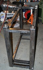
Here the caster pads are drilled and tapped and I spent some time cleaning up the surface rust using a combination of wire wheels on an angle grinder, some 3M scotch bright and a phosphoric acid based metal prep called “Right Stuff De-Ruster Metal Conditioner and Rust Preventer”:
LatheStand_101027_01

Comment on the Right Stuff. 

I’ve used it before a few times, and have been generally happy with it, but have to an extent ignored the directions before now.  It recommends brushing it on, leaving it and then painting over it, not fussing with it before painting.  Specifically recommending that the sticky surface that it leaves will actually help protect the steel and help the paint adhere.

Previously, I’ve basically stopped and sanded before, after, during… any time I had a rough spot.  If it looked like anything besides smooth steel it got sanded, sort of the sand and wipe down every step of the way approach and usually wipe down with something like a paint prep grease/wax/oil remover if there was any chance that I got some on it or got a hand print on it.  The Right Stuff has taken care of any surface/flash rust and I never had any issues with sanding afterwards.RightStuff

So this time I followed the directions.  After the initial clean up I put it on (used a combination of a chip brush and a but of scotch brite dipped in it) and after it dried I painted right over the surface it left.

Well, that was a mistake.  It dried with a bunch of brush marks and runs and the first coat of paint looked AWFUL.  Like as in it looked like I let a blind monkey paint it by splashing it on with a mop and a bucket.  I kept hoping all sorts of things were going to happen, none of them did.  After letting it sit over night, giving it a good hard look and deciding that I’m not going to be able to stand leaving it that way no matter how many coats of paint I put on it I ended up sanding down most of it till it was smooth.

I put it up on stands for painting and put the first coat on with it upside down to make sure all the bottom surfaces were well coated, and the second with it right side up.  For anyone wondering, that is grey Rust-Oleum Hammered:

LatheStand_101113_02

Yep, the hockey puck feet are installed, and wrapped in plastic bags so that the thing can be supported by something that does not get painted.

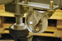
Here you can see one of the casters bolted in.  Before anyone says it, I know that that flange is probably a bit thin to hold those threads, but I didn’t seem to be having any problems with them and figured if I did it would be easy enough to add a nut on the back side.
LatheStand_101113_10

Oh, and the Grade 8, cadmium plated, washer head hardware is totally excessive (and I had to drill the mounting holes on the casters oversize to fit the bolts), but I have something on the order of 30# or more of these 3/8” bolts left over from a tape robot/server room decommissioning that I was involved with making those cheaper than standard 5/16” bolts and washers

So, what do you think?

LatheStand_101113_16

One last thing to do and the stand’s structure is done.  Drilling and tapping the top cross members for the lathe hold down bolts:

LatheStand_101113_19

Another idiot check to make sure that everything lines up:

LatheStand_101113_20

Next installment – The Top. 

Stay tuned, subscribe, tell your friends, pop some popcorn or grab a beer and hang out a while.

Wednesday, March 12, 2008

Rebuilding a 9 Bolt, 7.75” Borg Warner Cone Style Posi

This is basically a cleaned up version of a post that I made on thirdgen.org, the title links to the original thread. Like in other cases, I got a number of requests to put it back together with pictures, so here it is.

As always, the pictures are all clickable for a larger version.


Rebuilding the posi: There are pretty good, detailed instructions in the FSM and in the tech section on this site ( thirdgen.org ). Look them up, they’re a good start.

I’ll add a quick nutshell description and note where I did things differently/suggestions:

Disassemble: unbolt the axle retainers, pull the axles, pull the center section cover, remove the bearing caps (make sure that you remember what side everything came from so you can put it back like it came out), pop the carrier/ring gear assembly out of the housing. Note, this will require some prying and turning and make sure you save the side preload washers/shims so you can reinstall them like they came out. Be careful with them, they are machined out of a cast piece and can be brittle.

To perform the rebuild you need some kind of fixture to hold an axle. I took a chunk of wood, cut 2 shoulders to sit on top of my vice jaws, drilled a hole through the middle and then sliced it in half on the table saw to make some clamp/vise pads for the job:


Through the whole deal use the axles as alignment tools.


Before you disassemble it check this spot out:


It’s hard to see in that pic, but if the end of the cone is contacting the end of the case there your case is worn out of spec and you’ll either have to do some machining to it to make it work or get a new case.


With it sitting on the bottom axle, housing bolts up, unbolt the smaller, center bolts and pull the end of the housing/ring gear off.

When you do that you’ll see this (except you’ll have it in the case side, not the ring gear side like in this pic):


If you lift the spider/cross/preload spring assembly off you’ll get this:


If you lift that side gear out of the end of the case you’ll see the pocket in the side cone where you put the shims, there will be one on each side of the case between the side gear and the cone (unfortunately I don’t have a good picture). You can use any shims that are small enough to drop into the machined area between the 2 and still fit around the axle. I usually use 10bolt or ford 8.8” pinion shims. Actually, the last time I think I just stopped by the local machine shop and got a stack of whatever left over shims they had approximately the right diameter.

* This is where I differ from the instructions on the site or in the FSM, forget measuring clearances or anything else, just load both pockets with as much shim as you can get in there and still reassemble the case completely. I’ve never seen one of these get so tight it doesn’t work right (if anything you’ll want it tighter, not looser) and you’ll be kicking yourself if you do any less and start spinning one wheel again sooner then you had to. The shim packs will probably have to be the same thickness on both sides.

From there the reassembly is the opposite of the disassembly, just make sure that you have both axles installed and fully bottomed before torquing all the bolts, if you don’t line up the splines in the side gears and cones before then it’ll be next to impossible to do with it assembled.

Now if the case is worn out of spec, you can still usually get some life out it. What happens is that there are some rings machined into the end of the cones and the case to contact if the case is worn down too far, if you cut them down you can get some extra life out of it.

This is what it looks like if the cone and case ends are worn to the point where they’re grinding into each other, case side. The numbered parts were originally put in for something else, but they do point out the points that are contacting and wearing that aren't supposed to:


Cone side:


What I’ve done before is machine those down till they no longer contact (as a matter of fact, I think I machined them down till I had over .125” clearance). Again, case side:

Cone side:

FWIW, I did the inside of the case on a drill press with a surfacing disk and I did the cone side with an angle grinder by hand, just played with them till I got them within about .005 of flat… If I remember right I ended up cutting close to 1/4" total to make sure that everything fit (yes, this thing was way outside of spec, and yes, it still worked well after all this).

Eventually, after a few more rebuilds the cones/case will wear enough that they get too thin, and I started getting cracking around the opening that I mentioned to check above to see if it’s worn past spec. When that happened I pulled it all apart, bevel ground the sides of the cones, centered them up in the housing using the axles and welded them in, like this: