NOTE:
This has been a long, LONG time coming, I originally posted this the week of June 16-21, 2006 (yes, 4 years ago) on the Shop Floor Talk forums (http://www.shopfloortalk.com) and since the server that I hosted the pictures on went away I’ve promised people on and off for years that I’d put it all back together with the original pictures so they can see what I did. That said, I finally sat and did it, and actually I fixed the pictures to work correctly in the original post and am putting up a slightly edited version here.
A second thing to note is that since this was originally a forum post there was some conversation that I’m going to attempt to clean up here, which might make things disjointed since in some locations I posted pictures to answer questions. Also, this was 7 days of posts to the forum adding a little bit as the work progressed, so most of this was written not knowing how this will finally turn out which results in some vagueness in the beginning/middle.
If you want to see the original post it is here as long as they don’t move it.
I started putting together a pan/box press brake type thing (is there such a thing? There will be soon, the point being that the blade that does the bending can be replaced with one that is different lengths if I need to bend
into a box or pan shape with sides). The flat plate here is going to be the base and I’ll have some 1.5” angle welded to one side for sharp bends in sheet metal and some round stuff (probably heavy wall tube actually with round stock in the middle 6” to reinforce the center when bending heavy stuff, I don’t have enough solid round stock sitting around for more then a few inches and this is going to be a “no buck” project) welded to the other side for use with radius dies, bigger bends…

The holes in the plate were punched by the “previous owner” (a local welding shop that occasionally lets me dig through his scrap pile, I showed up and asked if he had a small scrap of ½” big enough to cut a turbo flange out of and he gave me 2 22x12” plates like this off of his scrap pile. The base plate is 22x8 (the width between the posts on my press is just over 22", maximizing my bending capacity for sheet metal), and you can see that the punched holes bent the corners a little bit, I straightened those in the press later on.
The shoe is actually only 18” wide (I’ll take care of that later, I have a plan) because that is what was left of that side of the plate after cutting out that turbo flange and working my way around another row of holes. The part that fits over the foot of the press is a chunk of 1-3/4” roll bar tubing salvaged from a roll bar pulled out of a race car, the slots in the side were cut on my little 4x6 band saw and welded with my little HH135. Oh, I cut all the ½” plate with my Rigid angle grinder and taking my time only used up 2 cutting wheels.
Not bad for a small 110V welder, huh:

FWIW, I checked after I fit everything up (it actually fit tight enough that you could tap it into place and didn’t have to hold it) and after I got it welded and I got no measurable bit of the tube being out of line with the plate, and only about .002” offset to one side…
I’d say that is way more accurate then it needs to be.
There is a problem here that someone might be able to help me with, those dark spots near the weld are real, they are actually dark sooty spots. What was happening was that running the welder full bore with a lot of wire feed was necessary to get nice welds on the heavy stuff, but as I was doing it the wire would actually melt the tip and would quit feeding, where I would get one of those dark sooty spots, get pissed off, pull out the pliers, open the welder, get the thing unmeleted, file down the contact tip, play with the feed…
I wish I could figure out why I’m melting tips. I’ve had a similar problem running some hot, big, overlapping weaved welds with a friend’s Lincoln SP 135, but in that case instead of melting the tip and screwing up the wire feed I actually had the last 1/8” of the tip just melt and disappear into the weld bead. Yea, I am running these welders at wide open, but the contact tips are also used on bigger welders so there has to be something else going on.
I ground the top and bottom edges of the shoe flat by hand using the 9” disc sander on my HF combination belt/disk sander:

That’s actually dirt on the ground edge, it’s really nice and shiny, measuring it it’s dead on 90* to the plate and there is about .008” difference between the middle and both edges- good enough. The top of the shoe was dead on where the socket for the press foot went. The other sides were trued and then nicely rounded over with a flap wheel (yes, I know, I’m anal retentive).
This is where my plan starts coming in (sorry for the cell phone pics, easier the dragging out the digital camera every time).

Those two pieces are some rails that I salvaged from a massive tape robot I dismantled at Sally Mae (real life I’m a “computer guy” systems/network engineer that quit that job for the time being, works at a speed shop, does systems/network consulting work afternoons/evenings and takes on some occasional custom fabrication jobs “in my spare time”). They are cad plated and I’m thinking are probably hardened and predrilled, they used to be what the robotic arms rode on in the tape silo.
I cut 2 sections of them 22” long (see, I’m telling you, I have a plan) with the holes staggered (the hole in one lines up with the center of the space between 2 hole in the other). I’ve drilled and started tapping the shoe to match these holes a little like this:

Actually, when it’s done the 2 rails will hang down below the flat edge of the shoe about 1” and be bolted on (the reason for offsetting the holes, so the bolts for each side don’t run into each other), the end result is that I can loosen the 2 rails and use them to clamp in any blade or die I want, so I can make them for sharp bends, radius bends, and even short "fingers" like a pan brake would have so that I can bend enclosed boxes/pans.
So my second real question… holding the shoe over the press “foot”
Originally I had the thought that I’ll drill and tap 2 3/8 course thread holes in the top edge of the shoe, and then use some hardened 3/8” all thread that I have, thread that into the holes and then drill matching holes in the cross rail that the hydraulic ram sits on in the press, so I could bolt it on using 2 wing nuts when I want to use it (even setup some stop nuts so I can make sure that it stays 90* to the base plate).
A bit cumbersome but safe and should be effective.
But, after searching for something to make that pocket out of, that tube is conveniently EXACTLY the same id as the foot on the press, so much so that it’s actually a slight press fit onto it (it stays on if you get it more then ¼” over it, but amazingly it’s such a smooth fit that it doesn’t mess up the paint on the press foot). With that nice a fit I’m almost tempted to use a set screw (use the same head size as the bolts for holding the 2 rails so I can have one dedicated tool to do anything I need with the thing, or maybe even weld a T or knob to it) or drill the whole thing, press foot and tube for a pin.
Any thoughts what would work best?
I played with it and another project instead of going to sleep… More fuzzy cell phone pics (they come out better if there is more light), but I figure that if I lost anyone in the descriptions these should catch them up.
Here is the shoe drilled and tapped for the rails… I used the center hole to line up both sides so even if I was off a fraction the holes would still line up:

I just put it in the press to hold it while tapping the holes… man, I need sharper taps or softer steel…
And here are a couple of pictures of the 2 rails bolted on and everything lined up. At this point I just need to make the blades (quite likely I’ll do one or 2 and save the rest for when I need them, and add the angle iron to the top side of that plate and the round pieces to the bottom. There is enough room between the 2 rails that whatever side I’m not using can drop down in the gap so I can make the base plate reversible:

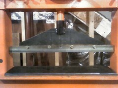
You can see here what I was talking about in the earlier post, that tube fits the foot of the press so well that it stays on there without moving. It’s actually tight enough that you can’t knock it off but you can sort of slowly twist it off without that much force. Again, I still haven’t decided which way I’m going to hold it on.
You can also see that it does fill the whole 22” of the press very nicely, there is just enough clearance on the sides that you can get it in without doing any real gymnastics, but that’s it. In the fourth picture I posted you can see a white sheet leaning against the side of the sawhorse, it’s a sheet of Teflon that I’m going to cut up and turn into pads for the side rails of the sled on the press, should just take up all the slop in it without allowing it to bind or rack.
Another thing I haven’t decided is that I’m probably going to make most (all?) of the blades for the thing out of ¼” plate… should be plenty with the rest of this holding it rigid, and it will make “tooling” for it cheaper. Since the gap between the bolt on rails is ½” I’m debating if I’m going to weld a strip of 1/8” to the inside of both of the rails and make the gap between them permanently ¼” or if I should do that to the blades and build them up to ½” where they slide in the pocket made by the rails.
I probably won’t have time to play with it today, but I should finish it over the weekend…
(A large part of this section was originally responses to questions asked by others on the forum, I cut out what I could without loosing information or making it unreadable)
So you guys are still out there… good to know I’m not alone…
Melting tips… yea, I’m running .023 wire, volts cranked and feed between 5-1/2 and 7-1/2 (out of 10, the only thing I’ve run faster on is with aluminum) depending on what is happening how it looks/feels (yea, I end up welding a lot of heavier stuff with my little welder).
Spatter, very little, I welded that wearing shorts sitting down with it over the edge of a trash can (read practically in my lap without getting burned) and the tip and guard/cup around it are staying relatively clean. I’ve got a tub of anti spatter gel but I’ve never used it since the one time I did with someone else’s welder I got the impression that the stuff dripped off into the weld and honestly I never really have much of a problem with build up. It seems like I can run miles of bead between cleaning tips and usually that isn’t because it’s too dirty and I’m having performance problems but because I’m anal retentive and just want it shiny.
Stick out… donno, I’ve been running pretty tight. Seems as I back off I loose power and penetration with the heavy stuff so I get in there, probably about ¼”. In this case the joint was basically a 90* angle/T joint so I couldn’t get all the way in, I doubt that I was closer then somewhere between ¼ and 3/8”. Really, in general I find that you have to keep things pretty tight with the little welders to lay a nice bead that doesn’t stick up too high.
Huh, I’m not sure what to try… my instinct is towards more wire speed (which should make for more spatter), or I think I have some .030” ER70S6 floating around (which I usually avoid since these little welders seem really tuned for the .023 stuff)
I think that I may have partially solved my problem. I found that ¾” black iron pipe is almost exactly 1” OD (seems like most of the press brakes that are sold use 1” round stock for the die), and that ½” almost fits inside it (sch 40 for both), like this:
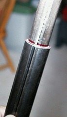
(notice that I cut a little slit in the ½” to fit over the seam/weld on the inside of the ¾. I also ended up carefully cleaning up the outside of the ½” on my belt sander making it slightly smaller… would have been much easier if I had access to a lathe at the time)
This is actually what the thing looked like: I cut the ¾” the full length, 22”, and then cut pieces of the ½”, 12” long to reinforce the centers, then I cut a groove up the middle of the ½, freehand, first with a cutting wheel and then I widened it with the edge of a grinding wheel in my monster Rigid 4.5” angle grinder (If you’re used to most of the HF grinders or like the typical Makita or Dewalt and you pick one of these up you’ll know what I mean. It’s got a reasonably sized housing but the thing is much more powerful, you can actually hear it spinning stuff up to a higher speed… the only one that I’ve used that was close was the 8.5A Milwaukee which I actually returned because of awkward ergonomics. FWIW, this Rigid was actually made by Metabo):

Heh, not bad for freehand, I have a better picture of the groove, but this one shows the end better, you can almost make out that I put the groove right dead on the weld seam figuring the tube was a little thicker there and I could cut a much larger groove without cutting through (It wouldn’t support the outer tube as well if it had a cut that could be squeezed) if I cut into the weld bead.
Now since the OD of the ½” is just a little too tight a press fit for the ID of the ¾ (it would work if you only had a piece about ½” long, but there is no way that the press would press 12” of it through. I could only get about 3/8” in with a 3lb drilling hammer when I test fit it), I actually took and ground it to size on the belt sander. My anal retentiveness kicking in again I actually measured them in 4 places and made sure that they were dead on to the accuracy of the dial caliper, shooting for a .002” interference fit (If I can press it together I don’t have to make any plug welds). This is what they looked like:

They pressed together perfectly, and even well lubed, after sitting 5 min they took a tight enough set that I couldn’t move them at all with the press. Took me about a 45minutes of puttering around to do (sort of messing with other stuff and playing with the dog… at the same time) and I have just over 1” OD and right around ½” ID now, I don’t think I’ll crush these easily.
There was a request for a pic of what I was talking about earlier, here is what I was going to reinforce somehow:

Now I’m going to probably still weld that angle iron to the bottom of the die, not worry about reinforcing it and use that side for more precise bends in thinner sheet metal, and weld the round dies to the other side to use for heavier pieces. I measured and made sure and both will just fit between the rails horizontal rails of my press and I’ll probably add little tabs on the sides to automatically center it when I drop it in.
So it’s done… sort of (done in the sense that it’s useable as it sits and I have other stuff to do so it will probably get used and modified/finished/painted some more as it goes).
This one shows a whole mess of things at once:

You can see that I added some spacers on the inside of the jaws to close down on a smaller blade. They have a threaded hole and are held in (not that they really need it but to make bolting it together a simple operation rather then trying to line up 5 pieces…) with the one bolt in the middle of each of the side rails.
Also, the only stock I had that I felt like using for the blade was some 3/16”, so since there was a ½” gap between rails the closest spacers were also 3/16”, but since I wanted to grab the blade and make sure that the blade is straight I ended up having to shim the side/clamping rails out with that combination. After digging for a while for something like some washers right around .030” thick I found that the bandsaw blade that I ripped most of the teeth off of in the trash can measured right around .028” (it was supposed to be .020”, grr harbor freight…), so with a little cutting and drilling it was declared a winner, you can see what I ended up with in that picture. With the teeth facing up the combination clamps the 3/16” thick blade perfectly.
Here you can see what I ended up with for the die assembly, and you can also see the blade:

Each side of the blade is beveled at a 50* angle so the included angle ends up being 80*, after thinking about this for a bit I just rigged a jig on my belt sander with 2 vise grips and a chunk of steel, making the angle perfectly repeatable across the whole length of the blade. The back side is just rounded so I can reverse it and put a nice radius bend.
The die, well, the angle iron on the top side in that pic is spaced apart about 1/8” and I ran a grinder through that gap to clean it up and pretty much consistent the whole length, this lets me do really sharp bends in thin stock, the other side lets me pretty much do anything else. I ended up doing some math and came to the conclusion that 2.4” spacing for the tubes will let me bend anything to greater then a 90* angle so I measured 2.5” and then put a new grinding wheel in the angle grinder and ran it up the inside of that line, making a trench maybe 5/16” or so the length of the piece that the pipe sat in to be welded (think a trench for the tube to locate in till it’s firmly welded). It ended up just about dead on where I wanted it when it was welded together.
Here is the whole thing assembled:

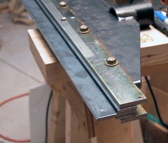
You can see how the parts stack together:
Finally, this is the whole deal in the press, with the angle iron side up for fine work:

And with the round side up for everything else:

You can see that I still haven’t really decided on retention, and really, it’s such a nice fit for the time being it really doesn’t need it.
I putzed around bending everything I could find all last night and it showed no signs of coming loose. I’ll probably just drill it and pin it just for safety reasons, but as of right now it’s not necessary.
Most of these setups have some sort of springs and side guides; from using the thing they don’t appear to be necessary with this setup, it didn’t show any real tendency to try torque over or do anything weird. The only issue like that that I ran into is that the shoe assembly is really heavy, enough to stretch out the return springs on the press carriage so that it does not retract the last 1”.
I plan on taking the carriage apart and modifying it. I’m going to add pads to the side guides and make some kind of bushing to fit the head of the jack into the pocket in the top of the frame tighter, right now both have about 1/8”-1/4” slack that is just annoying. When I do that I’m going to shorten the links that hold the springs to hopefully get it to return the whole way.
(note, that never quite happened like that, I ended up converting the whole thing to air over hydraulic, which added another set of springs on the cylinder and took care of all these issues)
One of the welds on the base plate/die is sticking up enough that when I have the angle iron side down it doesn’t want to seat perfectly flat… I’ll have to grind that down.
While I’m on the subject of welds I think I figured out my tip melting issues. I tried a few things with the .023” wire and finally had best results with some of the antispatter gel and the wire feed around 85-90… REALLY flying. The problem is that I was getting some really (I mean REALLY) crappy looking welds (they were structurally fine, but I couldn’t get them to look nice to save my life) like that (the bad ones are all on the round die side, facing away from the pictures. I’m not showing them to anyone ;-) ).
I finally decided to give up on the “the little 110v welders are optimized for the .02x” wire” thing and tried some .030” ER70S6…
WHAT A CHANGE!
It was a slight adjustment to get nice welds with it (it’s much faster and much more heat), but after the 2nd or 3rd bead I got to a happy place and started zipping along. I was still on the hottest tap (4) and the wire feed was still at a fast, 55, but hell, it worked, that’s how I got the welds like the ones on the front of the tube/plate in the last picture. I was surprised that I never ran up against the duty cycle of the little welder, I did end up generating enough heat in the thing that I actually melted the top 1-1/2” of the trash can I use next to the bench in the garage, which surprised me since if the welding table is tied up I often cut and weld on top of it and have never melted it before…


